
3D World | 214
Future Publishing
Project Info |
Publication | 3D World
Issue # | 214
Issue Date | Dec 2016
Lexicon | Publications
Created for | Future Publishing
Publication Specs |
Section | Expert Panel Q & A
Image Featured | Aerion Jet Interior
Page(s) | 74, 75
Responsibilities | Commissioned Article, 4-Part Tutorial w/ Visuals
Description |
Aerion Jet Interior was published in the December 2016 issue, #214, of 3D World magazine; one of the top trade magazines for the 3D industry.
In order to showcase my latest project, Aerion Jet Interior, I was asked to join the “Expert Panel” as part of the Q & A segment.
For this, I was commissioned to write a 420-word article which helps to answer a given question. I then
answer the question in the form of a 4-part tutorial, an “expert tip,” and supporting visuals to help explain the process.
Question |
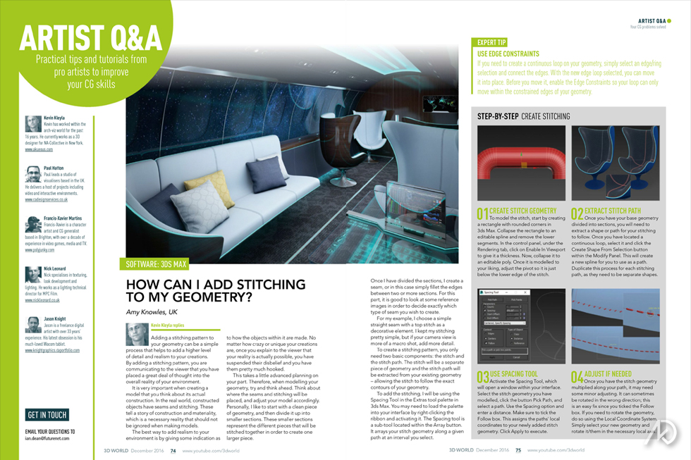
How can I add stitching to my modeled geometry?
Answer |
Adding a stitching pattern to your geometry can be a simple process which helps to add a higher-level of detail and realism to your creations. By adding a stitching pattern, you are communicating to the viewer that you have placed a great deal of thought into the overall reality of your environment.
It is very important when creating a model that you think about its actual construction. In the real-world, constructed objects have seams and stitching; or celebrated connections.
These connections tell a story of construction and materiality, which is a necessary reality that should not be ignored.
The best way to add realism to your environment is by giving some indication as to how the objects within it are made. No matter how
crazy or unique your creations are, once you explain to the viewer that your reality is actually possible; you have suspended their disbelief – you have them hooked.
This takes a little advanced planning on your part. Therefore, when modeling your geometry try and think ahead. Think about where the seams and stitching will be placed and adjust your model accordingly. Personally, I like to start with a clean piece of geometry, and then divide it up into smaller sections. These smaller sections represent the different pieces that will be stitched together in order to create one larger piece.
Once I have divided the sections I create a seam, or in this case, simply fillet the edge between two or more sections. For this part, it is good to look at some reference images in order to see exactly what type of seam you wish to create.
For my example, I chose a simple straight seam with a top stitch as a decorative element. I kept my stitching pretty simple, but if your camera view is more of a macro shot, you may want to add more detail.
To create a stitching pattern, you only need two basic components; the stitch and the stitch path. The stitch will be a separate piece of geometry and the stitch path will be extracted from your existing geometry – allowing the stitch to follow the exact contours of your geometry.
To add the stitching, I will be using the “Spacing Tool” located in the “Extras” tool-pallet. You may need to load the pallet into your interface by right clicking the ribbon and activating the pallet. The “Spacing Tool” is a sub-tool located within the “Array” button. It basically arrays your stitch geometry along a given path at an interval you select.
Steps |
01 | Create Stitch Geometry
To model the stitch, start by creating a rectangle with rounded corners. Collapse the rectangle to an editable spline, and remove the lower segments. In the control panel under the “Rendering” tab, click on “Enable In Viewport” to give it a thickness. Now, collapse it to an editable poly. Once it is modeled to your liking, adjust the pivot so it is just below the lower edge of the stitch.
02 | Extract Stitch Path
Once you have your base geometry divided into sections, you will need to extract a shape or path for your stitching to follow. Once you have located a continuous loop, select it and click the “Create Shape From Selection” button within the Modify Panel. This will create a new spline for you to use as a path. Duplicate this process for each stitching path; they need to be separate shapes.
03 | Use Spacing Tool
Activate the “Spacing Tool,” which will open a floating window within your interface. Select the stitch geometry you have modeled, click the button “Pick Path,” and select a path. Use the “Spacing” option and enter a distance which yields the best results. Make sure to check the box “Follow.” This will assign the paths’ local coordinates to your newly added stitch geometry. Click “Apply” in order to execute the command.
04 | Adjust If Needed
Once you have the stitch geometry multiplied along your path, it may need some minor adjusting. The stitch geometry can sometimes be rotated in the wrong direction; this is an easy fix since you checked the “Follow” box in the previous step. If you need to rotate the geometry, only
Expert Tip | Use Edge Constraints
If you need to create continuous loop on your geometry, simply select an edge/ring selection/connect the edges. With the new edge loop selected you can move it into place. Before you move it, enable the “Edge Constraints” so your loop can only move within the constrained edges of your geometry.