
3D World | 217
Future Publishing
Project Info |
Publication | 3D World
Issue # | 217
Issue Date | Feb 2017
Lexicon | Publications
Created for | Future Publishing
Publication Specs |
Section | Expert Panel Q & A
Image Featured | Art Bar
Page(s) | 64, 68, 69
Responsibilities | Commissioned Article, 4-Part Tutorial w/ Visuals, Video Tutorial
Description |
Art Bar was published in the February 2017 issue, #217, of 3D World magazine; one of the top trade magazines for the 3D industry.
In order to showcase my project, Art Bar, I was asked to join the “Expert Panel” as part of the Q & A segment.
For this, I was commissioned to write a 420-word article which helps to answer a given question. I then answer the question in the form of a
4-part tutorial, an “expert tip,” and supporting visuals to help explain the process. I was also commissioned to create a video tutorial which explains the process in more detail.
Question |
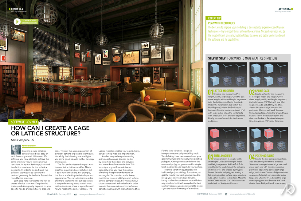
How can I create a cage or lattice structure?
Answer |
Creating a cage or lattice structure can be as easy or as difficult as you wish. With most 3D software you have ability to achieve the same or similar results with numerous variations. In my “Art Bar” image, I created two lattice structures for the spherical pendants. In order to do so, I used two different techniques to achieve the desired geometry for both the flat and the round lattice structure.
For my four-step tutorial I will offer each step as a different variation of how to create a lattice structure. Keep in mind that any solution greatly depends on your specific needs, and each has its pros and cons. Think of this as an exploration of different options or possible techniques. Hopefully the following steps will give you some good ideas to further develop and explore.
The first and easiest technique I want to cover is the “Lattice” modifier. This is great for a quick and easy solution, but it does have limitations. For example, the “Struts” are limiting in their shape and appearance. You can add/remove sides and make them smooth, but basically it is very rudimentary. Also, as with most lattice structures, there is a problem with how to resolve the corner vertices. The “Lattice” modifier allows you to add “Joints” as well to help hide this imperfection.
Another easy technique is creating a simple spline cage. You can do this by extracting the edges of a polygon and make the splines renderable. This technique is great for most shapes especially since you have the option of making the spline render radial or rectangular. You can also add a “Sweep” modifier or create a loft if you wish to have a more
complex shape. For my example I chose to start with a chamfer box in order to avoid the same awkward corner/vertex condition we have with the “Lattice” modifier.
For the third variation I begin to incorporate some poly-modeling tools. You definitely have more control over your geometry if you are manually manipulating polygons. Once you “Inset” and delete the unwanted polygons, you can add a simple “Shell” modifier to give some depth to your surface.
The final variation is just good, old-fashioned poly-modeling. Sometimes to get the results you want, you just need to roll-up your sleeves and get to work. It may not be the quickest or most efficient way possible, but it will always be the best solution because you decide what to create – you are not at the mercy of a modifier.
Steps |
01 | Lattice Modifier
Create a box measuring 6” in length, width, and height. Give the box 3 length, width, and height segments. Add the “Lattice” modifier to the stack. Under the “Parameters” tab within the “Modify” panel, select the “Both” radio button. Give the struts a radius of 1/16” with 8 sides. Make the joints “Octa” with a radius of 1/16” and 2 segments. Turn on “Smooth” for both struts and joints.
02 | Spline Cage
Create a chamfer box measuring 6” in length, width, and height. Give it 3 length, width, and height segments; it should have a 1/8” fillet with 4 fillet segments. Add an “Edit Poly” modifier. Select the central edge-loops of the perimeter fillets as well as all the non-filleted edge-loops. Click the “Create Shape” button. Select the editable spline and check-on “Enable in Renderer/Viewport.” Give the spline a 1/8” radial thickness.
03 | Shell Modifier
Create a box measuring 6” in length, width, and height. Give the box 3 length, width, and height segments. Add an “Edit Poly” modifier to the stack. Select all the polygons and “Inset” 1/16” and choose “By Polygon.” Delete the selected polygons leaving a flat, or single-sided surface, cage structure. Add a “Shell” modifier to the stack. Make the “Inner/Outer Amount” 1/16” for both values and check-on “Straighten Corners.”
04 | Poly Model
Create a box measuring 6” in length, width, and height. Give the box 3 length, width, and height segments. Add an “Edit Poly” to the stack. Select each non-perimeter edge-loop and move each 1/8” from each respective perimeter edge. “Ring” select each large edge, and “Connect Edges” with 2 segments. Select all non-perimeter edge-loops and “Chamfer” 1/16.”
Select the large interior polygons and “Extrude” -1/8” and delete them. “Bridge/Cap” all open edges.
Expert Tip |
Model Different
The best way to improve your modeling is to always experiment and try new techniques – model things differently each time. Not each variation will be the most efficient or useful, but it will lead to a new and better understanding of the software and its capabilities.